Documentation : F18 I/O
OUTPUT:
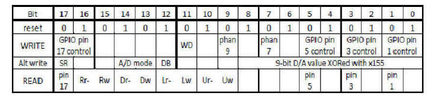
THE IO REGISTER: An 18-bit control and status register, named io and diagrammed below, is each F18A’s interface with its I/O circuitry (if any) and comm port handshake lines. In the “READ” line of the table below, the green background indicates signals that, if they exist, come from other nodes or the world outside
IO Register :
IO Register : Bits 17 16
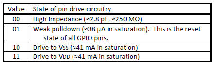
10000 io r! ( weak pull down )
30000 io r! ( drive pin High )
0 io r! ( high impedance )
In ArrayForth : Communication with GA144
host load panel
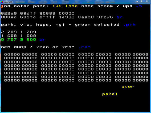
with node 500 ( GPIO-500.17 pin 7 )
talk 0 500 hook upd
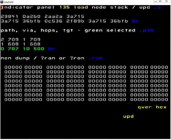
GPIO output :
0, 10000, 30000 {Hexa} io r!
!! Press F1 (decimal --> Hexadecimal)
Example :
10000 io r! ( weak pull down )
30000 io r! ( drive pin High )
0 io r! ( high impedance )
INPUT:
IO Register : Bit 17 read pin 17
GPIO input : !! Before write 0 ( High impedance )
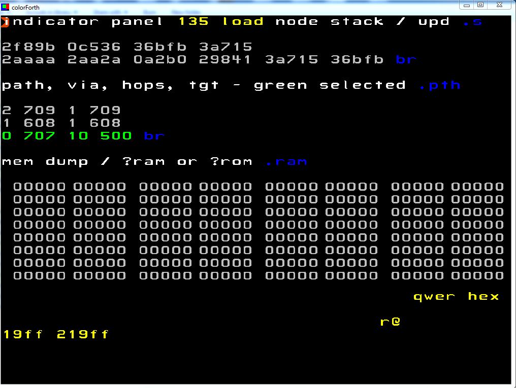
io r@
Exemple : Read when GPIO-500.17 = 0 , and when GPIO-500.17 = "1"
GPIO-500.17 = 0 19FF
GPIO-500.17 = '1' 219FF
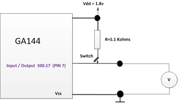
The schematic :
the switch is to put 1.8v on the GPIO 500.17