Documentation : F18 I/O
ANALOG OUTPUT:
The digital to analog converter (DAC) is a programmable current source that
can be used to generate a voltage across a resistance to ground, or to source an
op-amp. By writing the xor of a desired value and hex
155 into the low nine bits of io that value controls the DAC output. A
value of 1FF (written as 0AA) sets the DAC for
maximum current; a value of 0 (written as 155,
the reset state) sets minimum current, high impedance output. The typical DAC
transfer functions, in mV versus DAC values, into 75,
50, 37.5 and 8 Ohms are shown at right; as the
resistance decreases, the voltage decreases and the function becomes
more
linear. Analog nodes in F18A based designs have both ADC and DAC connected with
separate pins.
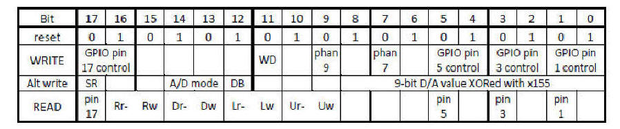
THE IO REGISTER: An 18-bit control and status register, named io and diagrammed below, is each F18A’s interface with its I/O circuitry (if any) and comm port handshake lines. In the “READ” line of the table below, the green background indicates signals that, if they exist, come from other nodes or the world outside
IO Register : 9-bits D/A value XOR x155 Bits 8 7 6 5 4 3 2 1 0
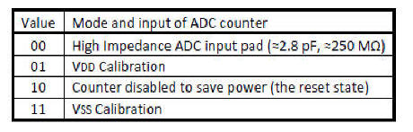
A/D MODE : Bits 14 13
In ArrayForth : Communication with GA144
host load panel
with node 117 ( 117 Analog 117.Ao , pin 50)
talk 0 117 hook upd
analog output :
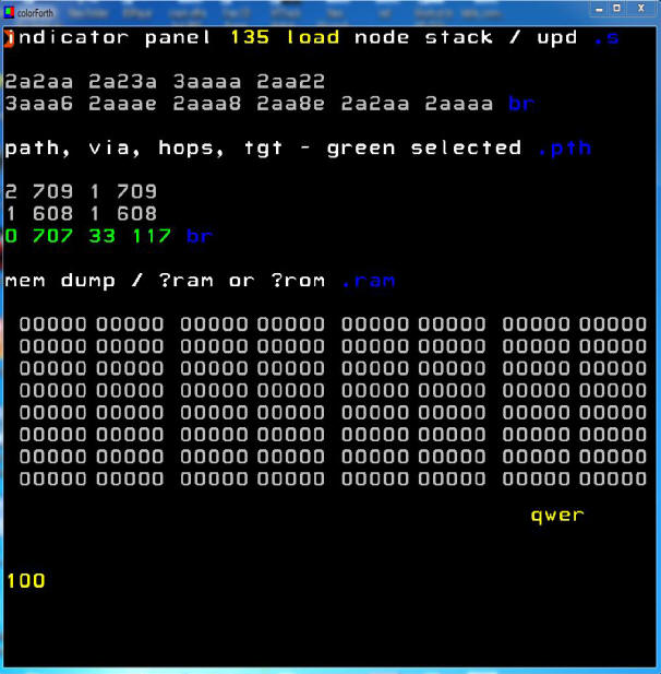
[0..511] {decimal} 155 {Hexa} OR io r!
Example : 100 155 OR io r!
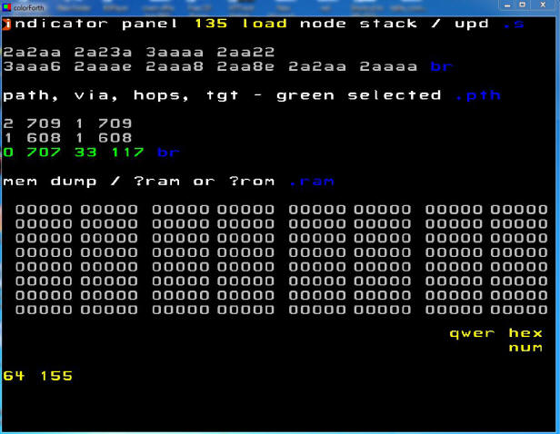
100
115 (Hexadecimal)
Press F1 (decimal --> Hexadecimal)
XOR
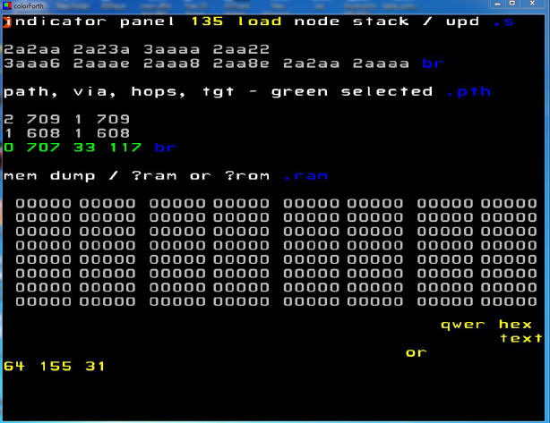
XOR result :
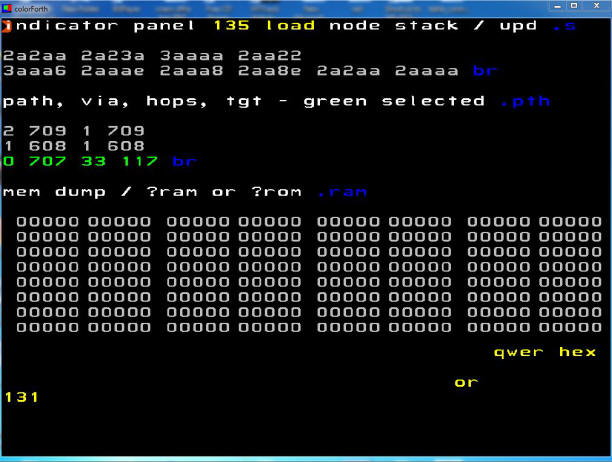
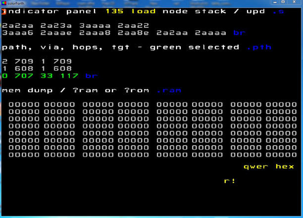
io
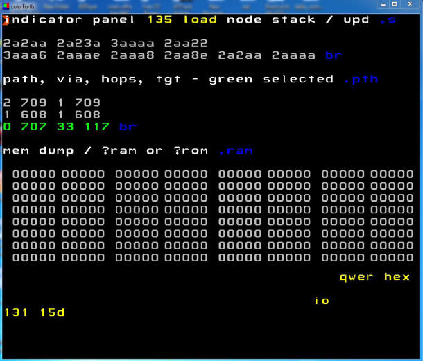
r!
You can measure between 117.ao (Pin 50) and Vss ---> V = 0.245 v for 100 (decimal)
The schematic :
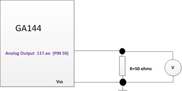
Several Measures : Analog Output 117.ao (Pin 50)
| Decimal Value | Hexadecimal | Hexadecimal XOR $155 | Measure (Volts) value R= 50 ohms |
| 0 | 0 | 155 | 0 |
| 1 | 1 | 154 | 0.002 |
| 10 | A | 15F | 0.026 |
| 50 | 32 | 167 | 0.125 |
| 100 | 64 | 131 | 0.244 |
| 200 | C8 | 19D | 0.47 |
| 300 | 12C | 79 | 0.665 |
| 400 | 190 | C5 | 0.837 |
| 500 | 1F4 | A1 | 0.977 |
| 511 | 1FF | AA | 0.99 |